Fluorescence-Control Unit: Difference between revisions
| Line 36: | Line 36: | ||
{| class="wikitable" | {| class="wikitable" | ||
|- | |- | ||
! Application !! Filter set !! light intensity set by LED current | ! Application !! Filter set !! light intensity set by LED current !!Position | ||
|- | |- | ||
| Amplex UltraRed(C) || AmR || 2 mA || 4 | | Amplex UltraRed(C) || AmR || 2 mA || 4 | ||
Revision as of 10:28, 25 April 2012

![]()


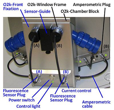
Fluorescence-Control Unit

| Description | Fluorescence-Control Unit with O2k-Front Fixation, Current-Control (O2k-Chamber A and B) for regulation of light intensity of the photodiodes in the fluorescence sensors. A component of the O2k-Fluorescence LED2-Module. |
|---|---|
| Product ID | 44100-01 |
| Type | O2k, MultiSensor, O2k-Fluorescence LED2-Module |
| Link | O2k-Fluorescence LED2-Module |
| Image |
O2k-Guide
Setup of the O2k-Fluorescence LED2-Module
- Switch off the O2k with the power switch on the rear of the O2k-Main Unit.
- Remove both blue O2k-Window Frames. Insert the O2k-Window Tool around the outer rim of the window frame and unscrew counter clockwise.
- Remove the Sensor-Guide (‘nose’) from the O2k-Front Fixation of the Fluorescence-Control Unit. Loosen the small fixation screw and pull out the Sensor-Guide.
- Place the Fluorescence-Control Unit below the O2k-Chamber Block. Align the windows of the O2k-Front-Fixation with the windows of the O2k-Chamber Block, re-insert the O2k-Window Frames, and screw them finger-tight onto the O2k-Main Unit.
- Re-attach the Sensor-Guide to the O2k-Front-Fixation. Fasten the fixation screw finger-tight.
- Place the power-cables from the rear of the Fluorescence-Control Unit in the middle below the O2k-Main Unit from front to rear. Unplug the mains power cable of the O2k and plug it into the female plug of the Fluorescence-Control Unit. Insert the male plug of the Fluorescence-Control Unit into the mains socket at the rear of the O2k.
- Connect the amperometric cables attached to the side of the Fluorescence-Control Unit to the ‘Amp’ plugs (labelled "NO" in Series D-E) on the O2k-Main Unit.
In this configuration the O2k can be used for high-resolution respirometry and fluorometry. It is not necessary to dismount the Fluorescence-Control Unit for basic HRR when a fluorescence singal is not recorded.
O2k-Guide: Setup - next step - Mounting a Filter-Cap
Power on
- Switch on the power of the O2k-Main Unit (rear).
- Press the power switch on the front panel of the Fluorescence-Control Unit. Check that the central green control light is on.
Control of LED-intensity
The light intensity of the LEDs is set by the current control, independent for each fluorescence sensor (O2k-Chamber A and B). The current is controlled by a switch on the front panel of the Fluorescence-Control Unit in a very wide range for optimization according to sample and fluorophore requirements:
- Position 0-8: (0) off, (1) 0.02, (2) 0.5, (3) 1, (4) 2, (5) 5, (6) 10, (7) 20, (8) 30 mA. The polarization voltage of the Amp-Channel (NO-Channel) is set to zero in DatLab [Oxygraph]/[O2k-Control].
- Position (9): variable, controlled by the polarization voltage setting in DatLab [Oxygraph]/[O2k-Control].
At higher LED-intensity the optical sensitivity is increased, i.e. the signal change per concentration change is enhanced. However, even moderately intensive light may exert negative effects: (i) Damage to the sample reducing the biological activity. (ii) Damage to fluorophores catalyzing degradation and various side reactions. Therefore, the LED-intensity should be kept as low as compatible with a smooth signal, i.e. when the resolution is just not limited by noise or disturbances. The values indicated in the table below are only suggestions to start with. It is recommended to optimize the light intensity specifically for each application.
| Application | Filter set | light intensity set by LED current | Position |
|---|---|---|---|
| Amplex UltraRed(C) | AmR | 2 mA | 4 |
| Safranin | Safranin | 1 mA | 3 |
| Magnesium Green(R) | MgG / CaG | 1 mA | 3 |
| Calcium Green(R) | MgG / CaG |
Amplification
The current from the photodiode is converted to a voltage and amplified by the gain setting in DatLab [Oxygraph]/[O2k-Control]. At a gain of 1, a current of 1 nA is recorded as a voltage of 1 mV (0.001 V). At gain 100, 1 nA corresponds to 100 mV (0.1 V). The amplified signal can be recorded in the range from -10 to +10 V.
O2k-Guide: O2k-Fluorescence_LED2-Module#Calibration